Next: 4.8 Conclusions Up: 4. Magnetization reversal in Previous: 4.6 Coercivity of Fe Contents
Thermal effects can also contribute to reduce the switching fields. The
dynamic dependence of the coercivity is usually analyzed using the
Sharrock law [Sharrock 90],
which is derived from the Arrhenius-Néel law. The application of
the Sharrock law requires the energy barrier dependence on the applied
field. In this section we evaluate that dependence and study the
thermal switching mechanism. We have calculated the energy barriers
values using the Lagrange multiplier method discussed in Section 2.3.6, but in this case we have used
the constraint ![]() , where
, where ![]() is the
average magnetization x component. This constraint has the advantage of
having the form of an applied field in the X direction, allowing to
obtain the energy barrier of an arbitrary applied field from the zero
field energy barrier value [Lu 07].
is the
average magnetization x component. This constraint has the advantage of
having the form of an applied field in the X direction, allowing to
obtain the energy barrier of an arbitrary applied field from the zero
field energy barrier value [Lu 07].
The saddle points as well as the energy barrier vary with the applied
field. Therefore, in this section we will refer to zero field saddle
points as, simply, saddle points. As in the field switching, the
thermal switching mechanisms are also different for different particle
widths. For the large aspect ratio particles the thermal switching
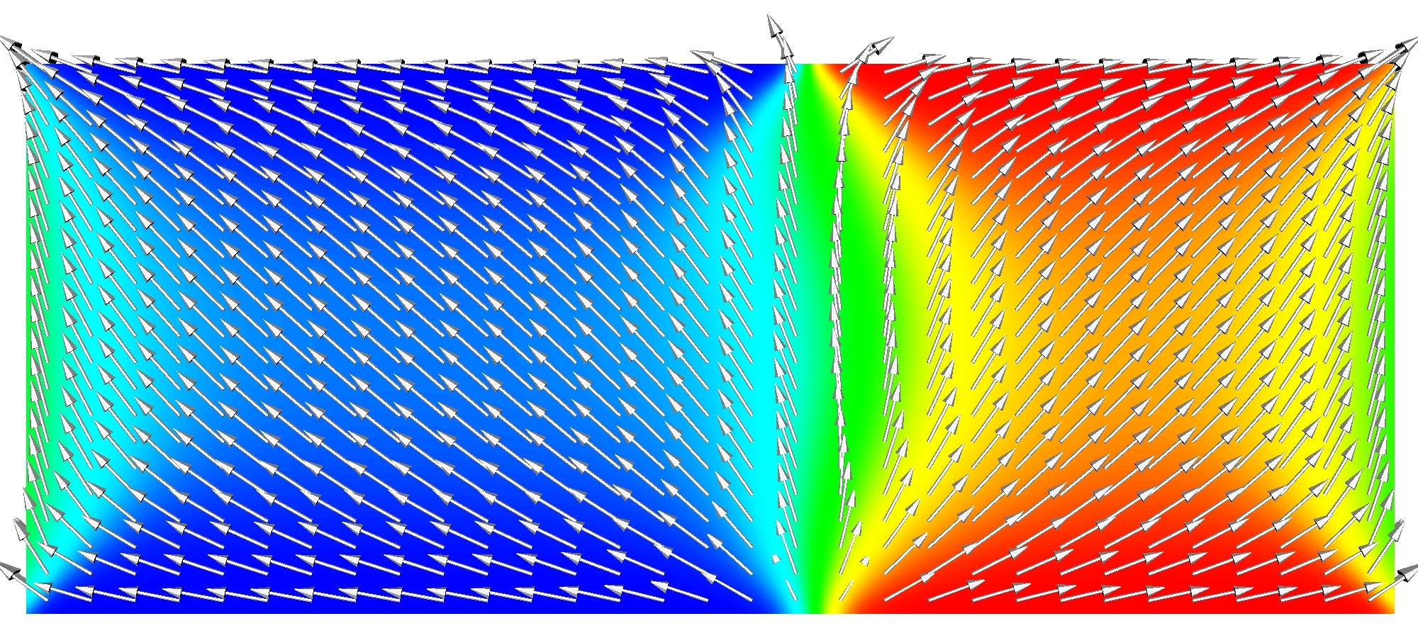
proceeds through a ![]() domain wall, as a saddle-point configuration shown in Fig. 4.16. The nucleation of the domain wall
starts from the structures that are created by the magnetostatics in
the particle ends (see Fig. 4.6).
In the small aspect ratio particles the saddle point configuration
consists of two domains, which point in one of the local directions of
the biaxial anisotropy, as shown in Fig. 4.17.
The domain wall is not located at the center of the particle since the
domain wall is stabilized in the center of the particle and such
configuration is a shallow minimum of the energy. This minimum is not
present if the particle presents any imperfection. As in the hysteresis
loops, the change of behavior is for a width ca.
domain wall, as a saddle-point configuration shown in Fig. 4.16. The nucleation of the domain wall
starts from the structures that are created by the magnetostatics in
the particle ends (see Fig. 4.6).
In the small aspect ratio particles the saddle point configuration
consists of two domains, which point in one of the local directions of
the biaxial anisotropy, as shown in Fig. 4.17.
The domain wall is not located at the center of the particle since the
domain wall is stabilized in the center of the particle and such
configuration is a shallow minimum of the energy. This minimum is not
present if the particle presents any imperfection. As in the hysteresis
loops, the change of behavior is for a width ca. ![]() and is related to the length of the
structures that minimize the magnetic charges. The zero field energy
barrier as a function of the particle width is plotted in Fig. 4.18(b). The domain wall mechanism yields
a linear dependence with the cross section. In our case there is a
change in the slope due to the different effective anisotropy, being
this slope larger for thinner particles due to their large shape
anisotropy. Finally, for small aspect ratio the effective anisotropy is
not dependent on the particle width obtaining a linear dependence of
the energy barrier.
and is related to the length of the
structures that minimize the magnetic charges. The zero field energy
barrier as a function of the particle width is plotted in Fig. 4.18(b). The domain wall mechanism yields
a linear dependence with the cross section. In our case there is a
change in the slope due to the different effective anisotropy, being
this slope larger for thinner particles due to their large shape
anisotropy. Finally, for small aspect ratio the effective anisotropy is
not dependent on the particle width obtaining a linear dependence of
the energy barrier.
![\includegraphics[width=\textwidth]{Capitulo4/Graficas4/ebarrierstot}](img708.gif)
|
||
|
![\includegraphics[height=6.5cm]{Capitulo4/Graficas4/scaling}](img709.gif)
|
![\includegraphics[width=\textwidth]{Capitulo4/Graficas4/hcsharrock}](img710.gif)
|
||
|
In Fig. 4.18 (a) the energy barrier values are shown as a function of the applied field value and the particle width. Several authors [Skomski 06] have found the applied field dependence of the energy barrier value to be:
From the scaling of the energy barrier value and the Arrhenius-Néel law, M.P. Sharrock [Sharrock 90] obtained the following expression for the thermal dependence of the coercivity, due to thermal relaxation during the hysteresis process:
![\includegraphics[width=\textwidth]{Capitulo4/Graficas4/saddle40}](img706.gif)
![$\displaystyle H_c(T)=H_c\left[1-\left[\frac{k_BT}{E_0}\ln\left(\frac{f_0 t_0}{\ln 2}\right)\right]^{1/n}\right]$](img715.gif)