Figure 4.14:
Position of the minimum of the energy with respect to the X axis as a
function of the stress for a SW particle with only biaxial
magnetocrystalline and magnetoelastic anisotropies.
|
|
Due to the extreme large plastic deformations originated during the
samples cold work, residual stresses can be present in the matrix
containing the nanoribbons. These stresses originate lattice
distortions that generate an additional term in the energy of the
nanoribbons. Clearly, this effect can modify the final coercivity of
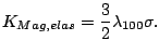
the nanoparticles. The expression for the magnetoelastic energy is:
 |
(4.3) |
where  is the
stress magnitude,
is the
stress magnitude,  and
and  are respectively the magnetization unit
vector and the cosine director of in the system of reference given by the
lattice axes, and
are respectively the magnetization unit
vector and the cosine director of in the system of reference given by the
lattice axes, and  and
and  are the
magnetoelastic constant. In the case of the nanoribbons the lattice is
rotated
are the
magnetoelastic constant. In the case of the nanoribbons the lattice is
rotated  with
respect to the long axis and supposing that the stress is applied along
the long axis of the particles we have
with
respect to the long axis and supposing that the stress is applied along
the long axis of the particles we have 
 .
For Fe the magnetoelastic constants are
.
For Fe the magnetoelastic constants are  and
and  [Bai 04].
The
magnetoelastic energy is then equivalent to an additional uniaxial
anisotropy (magnetoelastic) with easy axis in the Y direction and the
value:
[Bai 04].
The
magnetoelastic energy is then equivalent to an additional uniaxial
anisotropy (magnetoelastic) with easy axis in the Y direction and the
value:
 |
(4.4) |
The minimization of magnetocrystalline and magnetoelastic anisotropy in
the SW particle gives us the preferred direction of the magnetization
for the resulting mixed anisotropy. Fig 4.14
shows the magnetization angle with the long axis of the particle as a
function of the stress .
The original position of the minimum ( ) is at . For traction (positive values of ) the preferred
direction tends to
) is at . For traction (positive values of ) the preferred
direction tends to  (Y axis) and for compression (negative values of ) the preferred direction moves toward
  (X axis).
In Fig. 4.15 we present our simulational
data
for a ribbon, including both surface anisotropy (having an
effective constant  ) and a
magnetoelastic anisotropy arising from uniaxial compression
) and a
magnetoelastic anisotropy arising from uniaxial compression
 . The
magnetoelastic anisotropy in this case was directed parallel to
the ribbon axis. From the Figure it is clear that this
two-parameter (
. The
magnetoelastic anisotropy in this case was directed parallel to
the ribbon axis. From the Figure it is clear that this
two-parameter ( and ) fitting
renders the set
of data providing a better description of the experimental ones.
Nevertheless, without independent evaluation of at least one of
the considered parameter our simulation can not be used to
evaluate the second one.
and ) fitting
renders the set
of data providing a better description of the experimental ones.
Nevertheless, without independent evaluation of at least one of
the considered parameter our simulation can not be used to
evaluate the second one.
Figure 4.15:
Measured ribbon width dependence and the calculated
dependence of the coercive field including surface anisotropy and
magnetoelastic
anisotropy resulting from compression.
|
|
2008-04-04
![\includegraphics[height=6.cm]{Capitulo4/Graficas4/stressaxis.eps}](img686.gif)
![\includegraphics[height=7.cm]{Capitulo4/Graficas4/mixed.eps}](img703.gif)